Colour codes and Painting in HVAC

Piping Codes and Standards

This Section of the Specification sets out the requirements of painting & colour codes on HVAC projects.
GeneralOnly the best quality primers and paints shall be used. On special materials such as insulation the primer and paints shall be as recommended by the material manufacturer.

All items to be painted shall be first cleaned and prime coated.Over this the final colour shall be applied in two coats.The paint shall be gloss finish type.

On all non-metallic items, except insulation; the paint used shall be Acrylic Emulsion with mildew inhibitor additive.

Pipeline Colour Code

Compressors and Motors - Pale Blue
Switchboards and Control Panel - Hammer Finish Grey
Coolers and Condensers - White
Chilled and Condensing Water Pumps and Motors - Pale Blue
Fans and Air Handling Units - Pale Blue
Water Tanks - White

Fire Precautions and Control of Smoke in HVAC

Fire Safety

Scope
This section details the requirements to be provided in air conditioning systems to prevent the spread of Fire and Smoke to comply with the current requirements of the Chief Inspectorate of Fire Services.

Fire Damper

Wherever ducts pass through fire walls or connect to fire areas of a building, automatic fire dampers shall be installed in the positions indicated on the drawings.

The fire dampers shall be manufactured to comply with Australian Standard 1682 and tested and approved by the relevant standards authority in Australia. In addition the fire dampers shall be approved by the Chief Inspector of Fire Services. All locally manufactured fire dampers shall be individually certified by the Principals.

HVAC Electrical and Equipment Wiring with Accessories

HVAC Electrical and Equipment Wiring with Accessories

Introduction:

Modern life revolves around electricity, and proper electrical installations are essential for safety and functionality. In this comprehensive guide, we'll delve into the intricate world of electrical cable installation and wiring standards. From cable types to labeling, from conduits to earthing, we'll explore every facet of this critical discipline.


Table of Contents:

Cable Types and Acceptable Standards

Choosing the right cable type is crucial for electrical installations. Various standards such as PVC Insulated Cables (BS 6004), Armoured PVC Insulated Cables (BS 6346), Fire Resistant Cables (BS 6387), and MICC (BS 6207, Part 1) outline specific requirements for insulation, voltage, and application. Compliance with IEE Wiring Regulations ensures safety and performance.

MICC Cables and Installation

Mineral Insulated Copper Conductor (MICC) cables offer exceptional fire protection and high-temperature resistance. These cables consist of a copper conductor within magnesium oxide insulation and a solid copper sheath. Cold seal terminations with specialized components ensure secure connections. Installation involves meticulous jointing procedures and a focus on cleanliness and insulation integrity.

Halogen Free Fire Resistant Cables and Installation

Fire-resistant cables are integral for safety systems. They adhere to standards like IEC 331 and IEC 3323, designed to maintain functionality during fires. Brands like Radox, meeting fire safety requirements, are commonly used in critical applications.

Erection of Cables and Cable Laying

Erecting cables involves careful planning, including working drawings illustrating trunking/tray/conduit layouts. Proper cable dressing techniques prevent deformation and ensure optimal performance. Adequate support, proper bending radii, and spacing are crucial to maintain cable integrity.

Labels and Testing During Laying

Identifying cables through lead or aluminum labels is essential for traceability. Labels are placed strategically at switchboards and cable runs. Insulation tests during installation ensure quality, and test certificates from manufacturers validate compliance.

Conduits and Cable Trunking

Conduits and cable trunking provide protection and organization for cables. Galvanized conduits, complying with B.S. 31, are securely fixed to prevent movement. Proper bonding and earth continuity are maintained. Cable trunking, made from epoxy-coated mild steel, includes accessories for flexible cable management.

Cable Trays in Corrosive Areas and Fire-Resisting Barriers

In corrosive environments, cable trays and cables require anti-corrosive treatments to ensure integrity. Fire-resisting barriers, composed of non-combustible materials, seal openings to prevent smoke, gases, and fire spread, enhancing safety.

Radio Interference Suppressors and Earthing

Certain electrical equipment can cause radio and TV interference. Radio Interference Suppressors mitigate this issue. Comprehensive earthing practices, including bonding motor frames and mechanical plants, ensure equi-potentiality and safe operation.

Testing and Commissioning

The testing phase verifies the safety and functionality of electrical installations. Skilled personnel oversee tests, including insulation resistance, continuity, protective gear operation, and alarm devices. Detailed records and certificates ensure transparency and compliance.

Conclusion

Adhering to electrical cable installation and wiring standards is paramount for safety, reliability, and compliance. From selecting cables to comprehensive testing, every step contributes to a robust installation. Following the guidelines outlined here empowers professionals to create secure electrical systems that meet industry standards.

#ElectricalInstallation #WiringStandards #SafetyFirst #CableTypes #ProperInstallation #TestingProcedures #ElectricalSafety #ReliableSystems

HVAC Equipment Control System

Control System

The Controls supplied and installed on this Project shall be capable of meeting the requirements specified and functions required of them.

HVAC Control

All Controls, except those supplied as `Original Equipment' by the equipment manufacturer, shall be the standard product of one control manufacturer.

This Sub-Contractor shall be responsible for the correct operating ranges of all controls and the correct setting and adjustments to meet the designed conditions.

The Controls offered shall be either electric, or electronic type and the tenderers shall indicate the type being offered complete with all technical details and catalogues along with the tender.

Control of Noise and Vibration in HVAC

Noise and Vibration

This section of the Specification covers the Supply, Delivery, Installation and Testing of Noise and Vibration Control Equipment to be used in the isolation of the various mechanical equipment as called for in this specification.

It is the intent of this Specification that noise levels due to mechanical equipment and related services will be controlled to the design objectives stated herein, in all occupied areas. The requirements specified are considered to be the minimum precautions necessary to achieve these objectives.  The entire installation shall operate without objectionable noise and vibration as determined by the Engineer.

This Specification covers the supply, delivery to site, installation, commissioning and guarantee for two (2) years of the noise and vibration control equipment as described in the Specification including schedules of vibration control equipment and drawings.

The Sub-Contractor shall select and provide all mechanical equipment to the Specification, complying in particular with the requirements concerning balancing of the equipment, alignment of driving and driven units and operating speeds.

Refrigeration Piping in HVAC

Refrigeration

Refrigeration piping of this specification sets out the standards of workmanship and materials for the supply and installation of pipes and fittings for the Air Cooled Condensing System.

Piping Materials and Insulation

Refrigerant pipework of up to and including 2 in” bore pipes shall be of copper to BS 659.  Condensate drain pipes shall be of uPVC material.

The factory assembly plant shall be insulated as recommended by the manufacturer and applied at the manufacturer's factory during or after assembly.  The whole of the cold refrigerant pipelines installed at site including gas suction line, all fittings, solenoid valves, strainers, flanges, etc shall be insulated with minimum 1½" thick armaflex insulation or approved equivalent and vapour sealed with aluminium foil and painted with the appropriate and approved emulsion in two coats.

Condensate drain pipes shall be insulated with 1" thick armaflex insulation or equivalent material to approval.

Scope of Works in HVAC System

HVAC

The works covered by this specification consists of supply, delivery, off-loading, installation, testing, commissioning and One year's maintenance and guarantee of the Air Conditioning & Ventilation equipment.  In general this shall include but not be limited to the following:

a)     Supply and Installation of Fan Coil Units complete with all accessories to capacities shown on the Drawings and or Schedules.

b)       Supply and Installation of Air Handling Units to capacities shown on the Drawings or Schedules.

c)       Supply and Installation of all Supply and Return Air Ductwork complete with diffusers, flexible ducts, fire dampers etc as specified and as shown on the drawings.

d)       Supply and Installation of Toilet Ventilation System as shown on the drawings and as specified, complete with fans and controls.

Duct and Pipe Insulation in HVAC

Insulation

Description

Work of this Section shall conform to the requirements of the Contractor Documents.

Work Included

i.              Piping Insulation
ii.             Duct Insulation
iii.            Equipment Insulation

Submittals

Product Data: Manufacturer’s latest published data for materials, “R” values and installation.

Shop Drawings: Submit list of insulation to be used for each service.

Sound Attenuation in Ventilation Fans

Noise Pollution

Submit manufacturer’s latest published data for dimensions, materials, installation details and certified sound performance tests according to ISO 7235:1991(E) Standard.
Certification data for pressure drop and static and dynamic insertion loss based on tests of offered attenuator. The dynamic insertion loss shall of at least three different air velocity and the highest tested shall not less than 8m/s.

Submit airway velocity together with the face velocity of the offered attenuator and the airway velocity shall not exceed 11 m/s at any level of the specified Noise Criteria (NC) condition. However manufacturer shall control the air way velocity and not only the fan velocity at the offered attenuator to the proper level as related to the individual NC level specified.

Piping in HVAC System

Pipe

Description

Work of this Section shall conform to the requirements of the Air Conditioning Contractor Documents.

Work Included

  •  Air Vents & Drains
  •  Relief Valves
  •  Strainers
  •  Pressure Gauge
  •  Thermometers
  •  Anti-Vibration Coupling
  •  Drain Corks
  •  Chilled Water Expansion Tank

Exhaust Fan

Exhaust Fans

Fans shall be of the type, size, arrangement and capacity as indicated in the schedule and/or as shown on the drawings.
Unless specify, fans performance rating data shall be tested accordance with AMCA Standard 210-85 (Air Moving and Conditioning Association), ANSI/ASHRAE Standard 51-1985 “Laboratory Methods of Testing Fans for Rating”. Sound ratings shall conform to AMCA Standard 300-85, “Reverberant Room Method for Sound Testing of Fans”.
A computer printout of fan performance rating corresponding to the AMCA licensed data, with corrected ratings for altitude and temperature, fan operating speed, bearing life, etc. shall be submitted for approval.
All fans shall be dynamically trim-balanced to ISO1940 and AMCA 204/3 – G 2.5 quality grade after assembly. A computer printout with the vibration spectrum analysis not less than 12000 CPM (200 Hz) shall be attached to the fans.

Fan Coil Unit in HVAC System

FCU

Every model of Fan coil units offered shall have been tested and rated in sound and performance in accordance with ARI 443.70 and ARI 143.66 or equivalent. The certified ratings shall be submitted for approval. Samples, one of each model, shall be submitted for approval.

Basic Air Conditioning Units

The horizontal basic unit includes chilled water, cooling coil / heating coil, controls, main drain pan, auxiliary drain pan, fan board, industrial fan(s), fan housing(s), motor filter and thermal insulation.
The vertical basic unit includes chassis of galvanized steel, coil, removable fan boards/main drain pan assembly, auxiliary drain pan, fan(s), fan housing(s), motor and filter.
The main drain pan located under the coil shall have sufficient slope for positive and efficient drainage of condensate under all air conditioning conditions. A secondary drain pan shall be located under the position provided for mounting the control valve. The pans shall be of 1.2 mm (minimum) galvanized sheet steel and adequately insulated with fire retardant thermal insulation.
The chilled water cooling coil shall be of aluminium fins mechanically bonded to seamless copper tubes and tested with compressed air up to 2500 kPa under water.
Units shall be internally insulated with minimum 15mm, 32 kg/m3. density thermal and acoustic insulation.

Air Handling Unit in HVAC System

AHU

The packaged air handing units shall be factory assembled units in factory fabricated casings.
Each unit shall be complete with aerofoil centrifugal blowers, motors, drives and guards, cooling coil and drain pans, air filters, structural mountings, vibration isolators and all other necessary accessories.
The units shall be tested, rated and constructed in accordance with relevant ARI standard, ASHRAE Standard and America Safety Code B91. The blowers and cooling coils of the units shall have the specifications and capacity ratings as states in the technical schedule.

Duct System in HVAC

Duct System in HVAC | A Comprehensive Guide

In the realm of creating a comfortable and healthy indoor environment, HVAC (Heating, Ventilation, and Air Conditioning) systems take center stage. Among the integral components of an HVAC system, the duct system holds significant importance. It ensures proper airflow, temperature control, and indoor air quality. This article delves into the significance of the duct system in HVAC, exploring its components, installation process, and maintenance practices, all while emphasizing energy efficiency and environmental sustainability.


Table of Contents

  • The Significance of a Well-Designed Duct System
  • Components of a Duct System
  • Installation Guidelines
  • Standardization of Duct Fittings
  • Flexible Ducting: Balancing Flexibility and Efficiency
  • Energy Conservation and Duct Systems
  • Relevant Codes and Standards
  • Pros and Cons of Duct Systems
  • Conclusion
  • Hashtags
  • The Significance of a Well-Designed Duct System

    Imagine the duct system as the circulatory system of your HVAC setup. A well-designed duct system ensures that conditioned air is evenly distributed to every corner of a building. This promotes uniform temperatures and balanced air quality, preventing hot and cold spots and minimizing energy waste.

    Components of a Duct System

    Duct Materials

    Ducts can be constructed from various materials such as sheet metal, fiberglass, or flexible materials like fabric. The choice of material depends on factors like cost, insulation properties, and the specific requirements of the building.

    Joints and Seams

    Seams and joints in the duct system are critical points for air leakage. Proper sealing with sealant helps prevent conditioned air from escaping, optimizing energy efficiency and minimizing strain on the HVAC system.

    Insulation

    Duct insulation is crucial for temperature control and energy conservation. It prevents heat gain or loss as air travels through the ducts, reducing the workload on the HVAC system and ultimately cutting down on energy bills.

    Dampers and Valves

    Dampers and valves enable airflow control and temperature regulation. By adjusting these components, you can direct conditioned air to specific zones within a building, enhancing comfort and energy efficiency.

    Installation Guidelines

    Sizing and Layout

    A key aspect of duct system installation is sizing. Properly sized ducts ensure adequate airflow while avoiding excessive pressure drops. The layout should also be well-planned to minimize bends and turns, which can impede airflow.

    Sealant and Stiffeners

    Sealing joints with appropriate sealant prevents air leakage, maintaining the integrity of the system. Stiffeners are used to maintain the shape of ducts and ensure consistent airflow, promoting energy efficiency.

    Fastenings and Welding

    Mechanical fastenings like rivets, bolts, and nuts are used to connect duct sections securely. Welding may also be employed, but it requires careful consideration of material thickness and system airtightness.

    Standardization of Duct Fittings

    Standardization is essential for ensuring consistency and compatibility in duct fittings. Properly designed fittings, such as bends, branches, and tapers, contribute to efficient airflow distribution.

    Flexible Ducting: Balancing Flexibility and Efficiency

    Flexible ducts offer versatility in routing airflow, making them suitable for connecting terminal boxes and diffusers. Their installation requires attention to minimizing pressure losses and noise generation while ensuring proper support.

    Energy Conservation and Duct Systems

    Efficient duct systems play a pivotal role in reducing energy consumption. By preventing air leakage, optimizing insulation, and minimizing pressure drops, a well-designed duct system contributes to lower energy bills and a reduced carbon footprint.

    Relevant Codes and Standards

    For ensuring the highest quality and safety in duct system design and installation, adherence to relevant codes and standards is imperative. Notable standards include:
    • SMACNA - Sheet Metal and Air Conditioning Contractors' National Association
    These standards provide guidelines for duct fabrication, insulation, sealing, and installation practices.

    Pros and Cons of Duct Systems

    Pros:

    • Even airflow distribution
    • Enhanced energy efficiency
    • Improved indoor air quality
    • Temperature control and comfort

    Cons:

    • Potential for air leakage if not sealed properly
    • Inefficient layout leading to pressure drops
    • Incorrect sizing affecting system performance

    Conclusion

    The duct system is the backbone of any HVAC setup, ensuring the smooth flow of conditioned air and contributing to overall energy efficiency. With the right design, proper installation, and regular maintenance, duct systems can provide a comfortable and sustainable indoor environment while minimizing energy consumption and its impact on the environment.

    Hashtags: #HVAC #DuctSystem #EnergyEfficiency #IndoorAirQuality #EnvironmentalSustainability #TemperatureControl #Airflow #Insulation #Sealant #EfficientDesign #ComfortableSpaces

    Air Conditioner

    Portable Air Conditioner

    The split & ducted condensing units shall be with single compressors, each with its own independent refrigerant circuit couple with selected fan coil units (wall mounted, ceiling concealed, ceiling cassette or ceiling exposed type). The split units are completely factories packaged, wired and provided with shut off valves for convenient connection to the suitably selected direct expansion fan coil units.
    Each refrigerant circuit of this package shall be constructed using copper piping with brazed connections; joining compressor, condenser coil, filter drier, sight glass, thermo-expansion valve and evaporator cooling coil in a completely sealed loop. The refrigerant circuit shall also be factory leak tested, dehydrated, evacuated and pre-charged with R410A.
    The air-cooled condensing section shall consist of the compressor(s); condenser coil; centrifugal condenser fan(s) with motor and drive assembly, factory packaged switchboard, safety and operating controls.
    The evaporator blower section shall consist of the direct driven centrifugal blower fan and motor assembly; direct expansion coil complete with thermo-expansion valve(s), remote controller and a filter frame for flat filters.

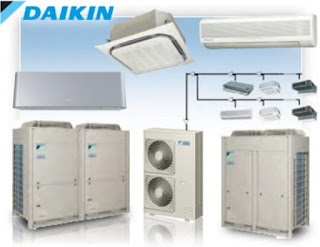
    Air Conditioner with Multi Split AC

    Air Conditioner

    Image Source: Daikin
    The multi-split condensing units shall be with multiple compressors, each with its own independent refrigerant circuit couple with selected fan coil units (wall mounted, ceiling concealed, ceiling cassette or ceiling exposed type). Multi split units are completely factories packaged, wired and provided with shut off valves for convenient connection to the suitably selected direct expansion fan coil units. Each refrigerant circuit of this package shall be constructed using copper piping with brazed connections; joining compressor, condenser coil, filter drier, sight glass, thermo-expansion valve and evaporator cooling coil in a completely sealed loop. The refrigerant circuit shall also be factory leak tested, dehydrated, evacuated and pre-charged with R-22. The air-cooled condensing section shall consist of the compressor(s); condenser coil; centrifugal condenser fan(s) with motor and drive assembly, factory packaged switchboard, safety and operating controls.
    The evaporator blower section shall consist of the direct driven centrifugal blower fan and motor assembly; direct expansion coil complete with thermo-expansion valve(s), remote controller and a filter frame for flat filters.

    Cooling Towers

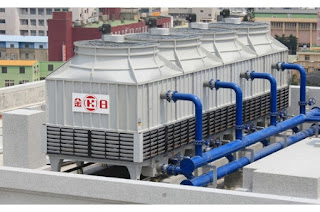
    Cooling Tower

    Image Source: www.kingsunct.com
    The Cooling Towers to be used on this project shall be of acceptable manufacture. All Cooling Towers supplied and installed should be certified by the Cooling Tower Institute of America or Japan Cooling Tower Institute. Only Cooling Towers made by the Principals are acceptable. Locally made Cooling Towers are only acceptable if they are specifically certified by the Cooling Tower Institutes of America or Japan.
    Performance And Guarantee Of The Cooling Towers

    Centrifugal Pump

    Pump

    The pumps used shall be in general & conform to the following specification and applies to Centrifugal pumps only.
    Casing
    Image Source: www.made-in-china.com
    End Suction Centrifugal Pumps
    The casing shall be of heavy close grained cast iron, to withstand high tensile strength with smooth waterways and fitted with bronze wear ring. It shall be of vertically split design with streamlined volute and integral suction vertical position to facilitate piping. Casing shall have tapped openings for perming, vent, drain and gauge connections.

    Horizontally Split Case Centrifugal Pumps
    Image Source: www.directindustry.com

    The casing shall be of heavy close grained cast iron of high tensile strength, and shall be split parallel to the shaft. Bearing housing supports, suction and discharge flanges shall be cast, bored and machined generally with the lower half and bolted together. This removable upper half casing and bearing caps should permit inspection or removal of the entire rotation assembly without disturbing the piping. The flanges shall be to BS4504-1968.

    Impellers
    The impellers on end suction pumps shall be semi-open type carefully balanced for smooth operation. Balancing openings shall be provided near hub of the impeller to reduce pressure on the stuffing box to approximately suction pressure. The impeller shall be secured to the shaft by feather and nut.

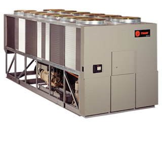
    Air Cooled Chiller

    Chillers

    This section of the specification details the requirements of materials, workmanship and other accessories in respect of Air Cooled Chiller Units.

    Image Source: Trane
    Casings
    The chiller unit shall consist of galvanised steel cabinet mounted on a frame, the whole of which shall be rust proofed and finished with a scratched-resistant and wear resistant baked on enamel so as to resist marine environment corrosion. Removable panels shall be provided to enable all maintenance and repairs to be carried out without removal of the unit or structural alteration to prevent rattles and looseness after prolonged period of operation. 

    The inside of the cabinet (where the compressor is located) shall be insulated with 2” thick high density fiberglass or Rockwool. The nuts and bolts shall be treated with anti rust and coat with rust proof paint.

    Popular Industrial Chiller Manufacturers
    • Trane Air Cooled Chillers
    • Carrier Chillers
    • Hitachi Chillers
    • Mcquay Chillers
    • Dunham Bush Chillers
    • York Chillers
    • Clivet Chillers
    • Daikin chiller

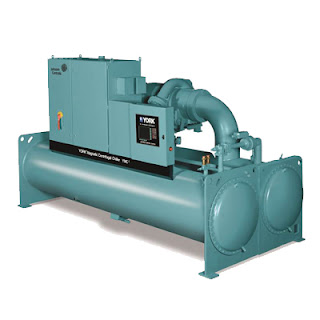
    Water Cooled Chiller in HVAC: Enhancing Energy Efficiency and Performance

    Water Cooled Chiller in HVAC: Enhancing Energy Efficiency and Performance

    Introduction

    Water cooled chillers play a pivotal role in the HVAC industry, offering efficient cooling solutions for various applications. As the demand for energy-efficient systems rises, it's essential to understand the technical aspects and benefits of water cooled chillers in the HVAC sector.

    Table of Contents

  • Packaged Chiller Units
  • Packaged Chiller Units
  • Compressors
  • Purge Or Pumpout System
  • Cooler (Evaporator)
  • Condenser
  • Unit Control Panel
  • System Control Panel
  • Vibration Isolation Mounting
  • Performance Testing In Factory
  • Refrigerant
  • Warranty
  • Packaged Chiller Units

    Water cooled chiller units are designed to provide efficient cooling through the use of centrifugal or screw compressors, motors, coolers, condensers, and control equipment. These units are meticulously assembled, tested, and charged with refrigerant and lubrication oil before shipment.

    Exploring Key Market Players in the HVAC Industry

    When it comes to the HVAC industry, several market players have established themselves as leaders in providing innovative solutions for heating, ventilation, and air conditioning needs. These companies contribute significantly to shaping the landscape of indoor comfort and energy efficiency. Let's delve into some of the key market players in the HVAC sector:

    • York Chillers: York is renowned for its diverse range of cooling solutions, catering to residential, commercial, and industrial spaces. Renowned for their dependability and cutting-edge features, their products stand out in the market.
    • Carrier Chillers: Carrier is a global leader in HVAC solutions, offering cutting-edge technologies that focus on sustainability and energy efficiency. They have a strong presence in both residential and commercial markets.
    • Trane Chillers: Trane stands out for its commitment to innovation and environmental responsibility. They provide a wide array of HVAC systems known for their reliability and smart controls.
    • Hitachi Chillers: Hitachi is recognized for its energy-efficient cooling solutions that prioritize both performance and environmental impact. They offer a range of options suitable for different applications.
    • McQuay Chillers: Acquired by Daikin, McQuay continues to be a prominent player in the HVAC industry. They offer comprehensive solutions for heating, cooling, and ventilation needs.
    • Daikin Chiller: Daikin is a global leader that emphasizes advanced technology and environmental sustainability. Their HVAC products are designed to deliver optimal comfort while minimizing energy consumption.
    • Clivet Chillers: Clivet focuses on eco-friendly and energy-efficient HVAC solutions. They provide systems that cater to various sectors, including residential, commercial, and industrial.
    • Dunham-Bush Chillers: Dunham-Bush specializes in air conditioning and refrigeration solutions that prioritize performance and reliability. They present an extensive array of products suitable for various applications.

    These market players play a crucial role in driving innovation in the HVAC industry. Their products and solutions contribute to creating comfortable indoor environments while adhering to energy efficiency and environmental standards. As the demand for sustainable HVAC solutions continues to grow, these companies remain at the forefront of shaping the industry's future.

    Compressors

    The heart of the chiller system is its compressor. The compressors can be either single-stage or multistage, and they should be designed for quiet operation and maximum efficiency. The use of helical gears, aluminum alloy impellers, and shrouded impellers helps achieve optimal performance. Capacity control is often managed by inlet guide vane assemblies to ensure efficient modulation.

    Purge Or Pumpout System

    Units operating with refrigerant under vacuum require a reliable purge system to manage non-condensable gases and water. A well-designed system with proper alarms, controls, and maintenance provisions ensures the longevity of the equipment and efficient operation.

    Cooler (Evaporator)

    The evaporator, a crucial component in the chiller unit, demands high efficiency. A well-designed cooler with copper tubes, external fins, and integrated mist eliminators ensures optimal heat exchange and reliable performance. Proper insulation of cold surfaces prevents energy loss and ensures efficient operation.

    Condenser

    Similar to the evaporator, the condenser must be designed for efficient heat exchange. Copper tubes with external fins, along with proper water connections, ensure effective cooling. The use of horizontal shell and tube design allows for individual tube replacement, making maintenance more manageable.

    Unit Control Panel

    The microprocessor-based control system enhances the chiller's performance and energy efficiency. With features such as precise temperature control, load management, and communication capabilities, the unit control panel offers advanced functionality. The display, interface, and monitoring options contribute to smooth operation and diagnostics.

    System Control Panel

    For installations involving multiple chillers, a system control panel is invaluable. It optimizes the coordination and operation of parallel chillers, ensuring efficient load distribution and energy savings. The panel's scheduling capabilities, energy-saving strategies, and communication interfaces enhance overall system performance.

    Vibration Isolation Mounting

    Vibration isolation mounting helps minimize noise and vibrations generated by chiller operation. This not only enhances the system's performance but also contributes to the comfort and well-being of building occupants.

    Performance Testing In Factory

    Precise testing of chiller performance in the factory is vital to ensure compliance with specifications and guarantees. Performance tests cover various aspects, including water flow rates, temperatures, power consumption, and more. These tests provide essential data for validating efficiency and capacity.

    Refrigerant

    The choice of refrigerant is critical in line with environmental concerns. Refrigerants compliant with environmental agreements, such as R123 or R134a, ensure the chiller's eco-friendliness. Manufacturers should provide clear guidelines for refrigerant selection and its impact on the chiller's performance.

    Warranty

    The compressor and motor warranty is crucial for long-term reliability. The warranty terms vary based on the RPM of the compressor, ensuring that these components are protected and well-maintained over time.

    Conclusion

    Water cooled chillers stand as essential components in the HVAC landscape, contributing significantly to energy-efficient cooling solutions. Understanding their design, components, and operation is key to harnessing their full potential. By focusing on optimal compressor design, efficient heat exchange components, advanced control systems, and eco-friendly refrigerants, the HVAC industry can continue to enhance energy efficiency, reduce carbon footprints, and provide reliable cooling solutions for various applications.

    Hashtags: #HVAC #Chillers #EnergyEfficiency #CoolingSystems #BuildingAutomation #SustainableTech #GreenHVAC #ClimateControl